The tooling was custom.
The engineering didn’t have to be.
A recurring turbine balancing-tooling process that could consume weeks of expert engineering was converted into a reusable system that encoded the balancing method, configured the tooling, and generated the manufacturing package in minutes.
Start here
What are you trying to build or improve?
Tell us what you're working on, what you're trying to accomplish, and what is getting in the way.
Before
2+ weeks
engineering cycle
After
Minutes
new configuration
Scale
50+ configs
reusable tooling

The Challenge
The geometry changed. The engineering pattern did not.
Each turbine blade configuration required custom moment-weight tooling. The fixture had to establish the correct center-of-gravity and moment condition for that blade, yet the legacy process relied heavily on expert judgment, repeated calculations, and trial-and-error adjustment.
TIME
Engineering dominated lead time
A new tooling configuration could take more than two weeks to design even though the underlying problem class was familiar.
KNOWLEDGE
Expert judgment repeated manually
Engineers had to infer where balancing weight belonged, then adjust and recheck the fixture rather than drive the answer directly from known blade properties.
VARIATION
Customization was unavoidable
Blade geometry, mass properties, required moment correction, and packaging constraints could change the fixture family, puck count, puck size, and puck location.
The Insight
The product was custom. The design logic was reusable.
The opportunity was to stop treating each fixture as a drawing exercise and instead encode the engineering method: use blade-model properties to establish the target condition, calculate the balancing scheme, select the appropriate fixture family, and let those decisions drive the tooling.
The real breakthrough was not faster modeling. It was turning an expert, trial-and-error balancing process into a repeatable engineering system.
The system didn’t automate a drawing. It encoded the balancing method.
The Engineering System
Make the expert logic explicit, then make it reusable.
The automated system linked the blade’s known engineering properties directly to the physical tooling decisions and the manufacturing package.
01
Blade CAD + mass properties
Geometry, center of gravity, moment data, and other model properties.
02
Target moment condition
Calculate the correction rather than find it by trial and error.
03
Fixture family
Select the appropriate architecture from model and packaging requirements.
04
Puck count + size + placement
Determine the physical balancing scheme automatically.
05
CAD + BOM + drawings + CTQs
Generate the manufacturing and inspection package.
Engineering in the Real World
Locate it. Balance it. Calibrate it. Reuse it.
The tooling, calibration artifacts, and moment-weight equipment all had to work as one controlled system.
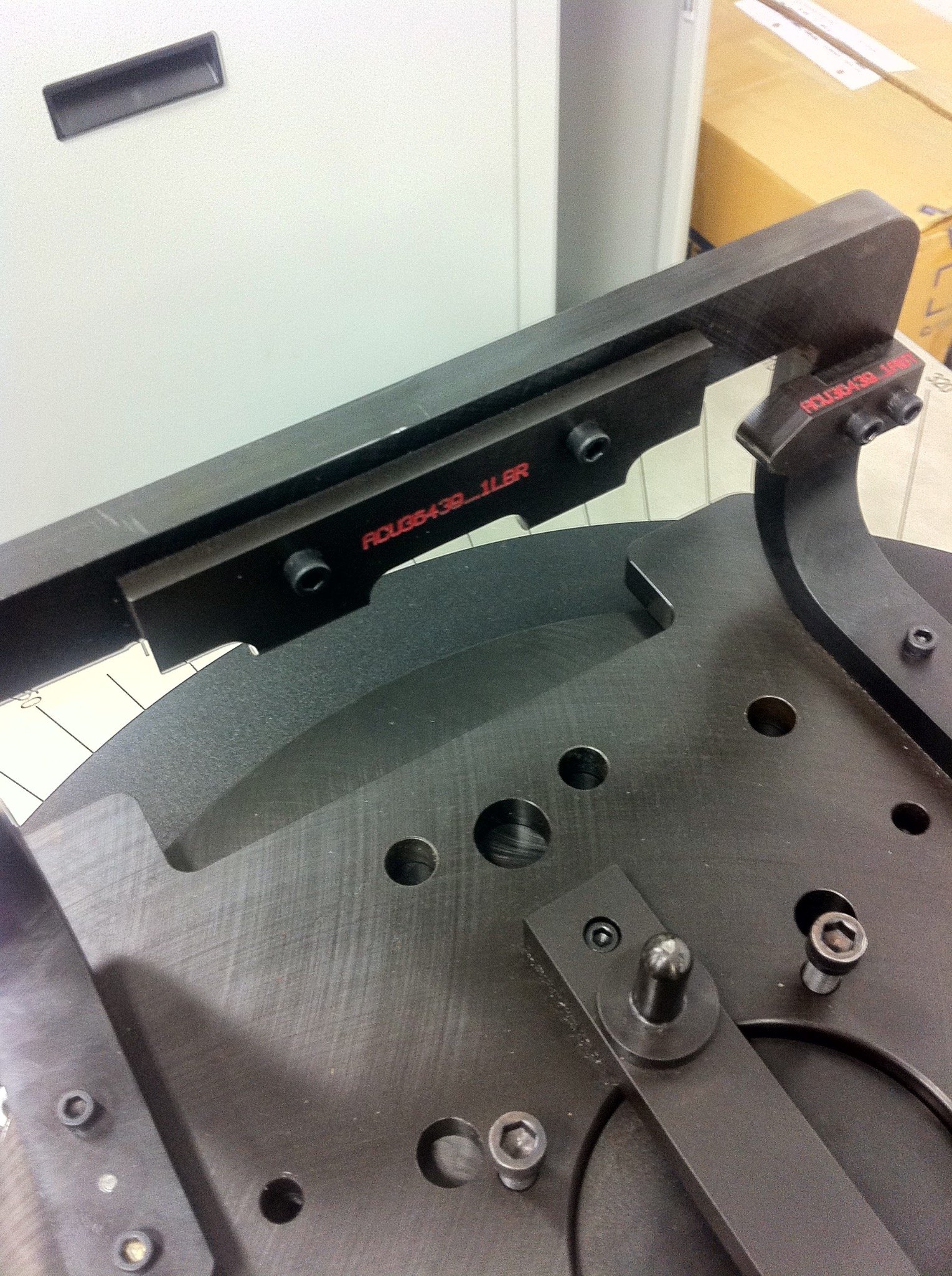
REPEATABLE LOCATION
Two round features locate the blade-root serrations, with separate axial and radial datums establishing the loaded blade consistently before balancing.
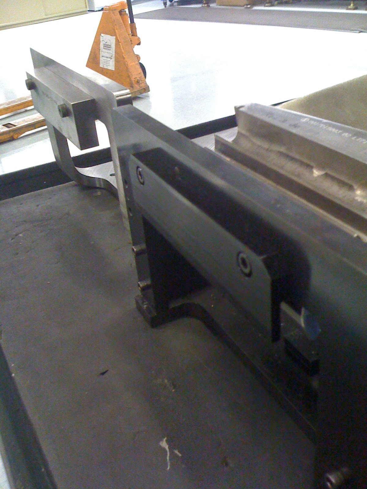
BEFORE + AFTER
The older one-off tooling is shown at right and the newer reusable approach at left, making the physical architecture change visible.
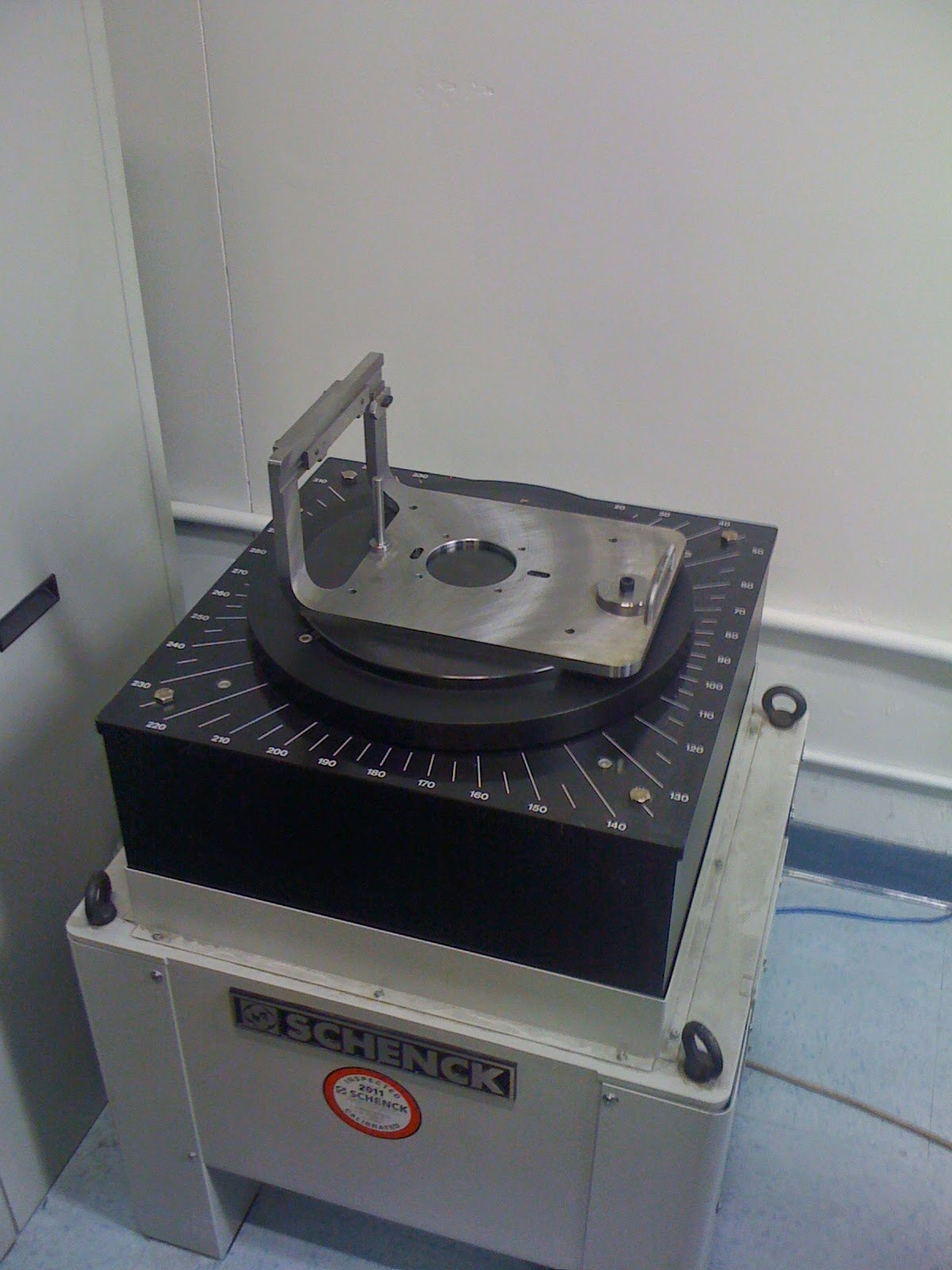
MOMENT-WEIGHT SYSTEM
The reusable fixture mounted to moment-weight equipment adapted from a tire-balancing system, connecting the calculated balancing condition to the physical process.
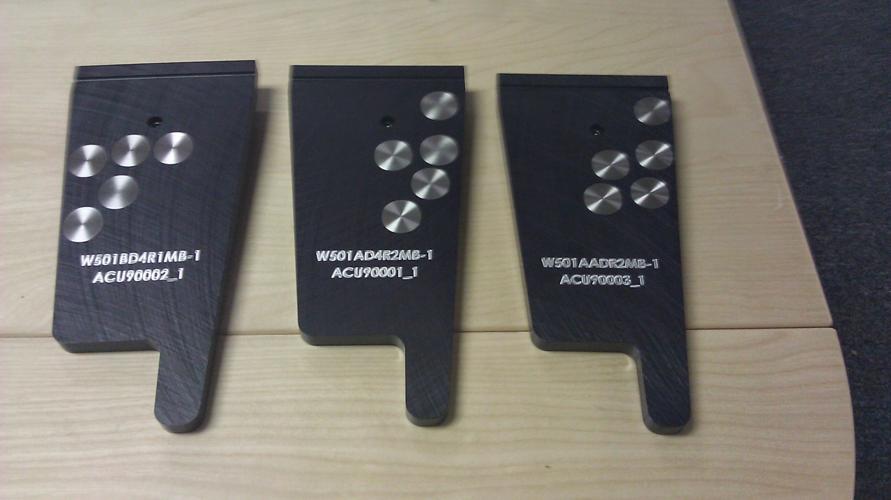
CALIBRATION FAMILY
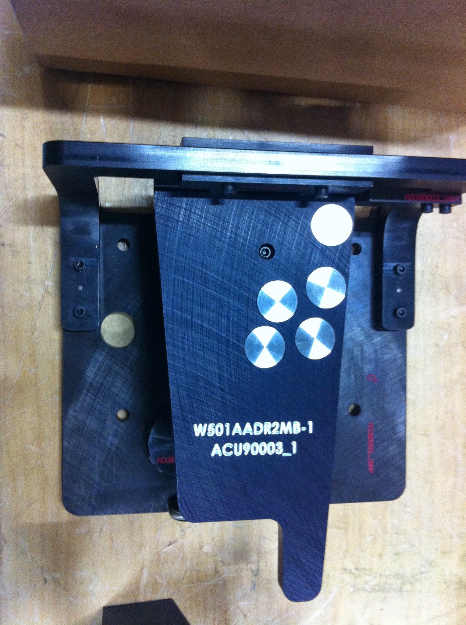
Configuration-specific blade simulators reproduced relative mass locations so the weighing system could be tared and periodically calibrated across different blade types.
CALIBRATION IN THE SAME SYSTEM
The simulator used the fixture, not a separate calibration concept.
The parametrically driven simulator installed directly into the newer tooling architecture, tying calibration, fixture location, and the balancing process together as one reusable engineering system.
The Result
The lasting output was capability, not a faster fixture.
The balancing method itself—mass-property interpretation, fixture-family selection, puck count, sizing, placement, calibration support, and manufacturing documentation—was captured in a reusable system.
Engineering Cycle
2+ weeks
Minutes
Configurations
50+
blade configurations supported
Typical Tool Cost
$4k–$5k
<$1k
Why It Matters
Automation is valuable when it captures engineering judgment.
The leverage came from identifying the reusable structure of the physical problem, then embedding that knowledge in a system others could use.
The system made a difficult engineering task look easy because the difficult thinking had already been done—and preserved.
That is the difference between automating CAD work and building reusable engineering capability.
Related Problems
This case is the clearest example of Telodyn’s reusable-platform work.
05
Reusable Engineering Platforms
When every variant triggers another engineering cycle even though the underlying rules repeat.
02
Prototype to Production
When engineering knowledge must become repeatable product and process behavior.
03
Low-Volume Manufacturing Systems
When specialized work needs repeatability without mass-production infrastructure.